☷ Product Description
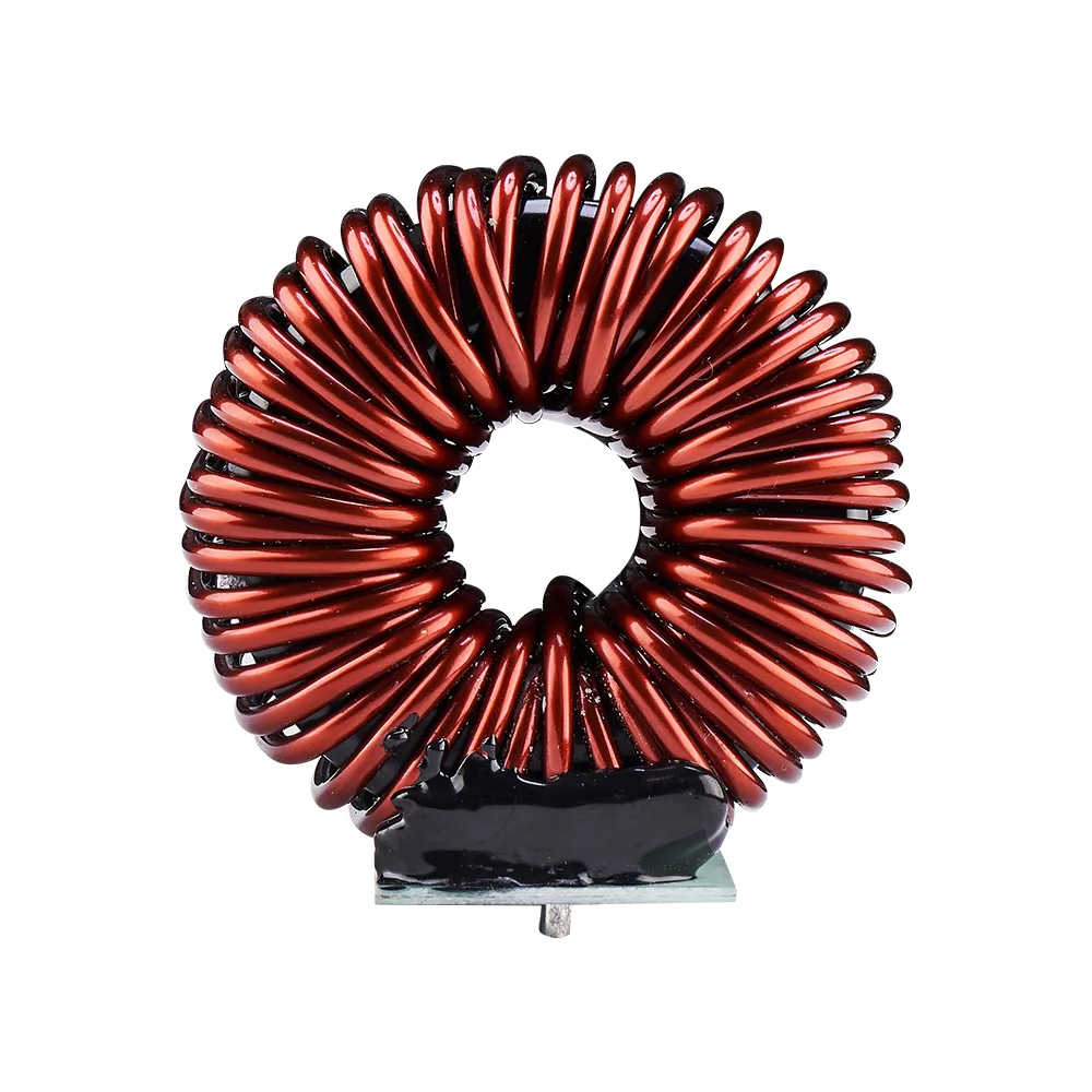
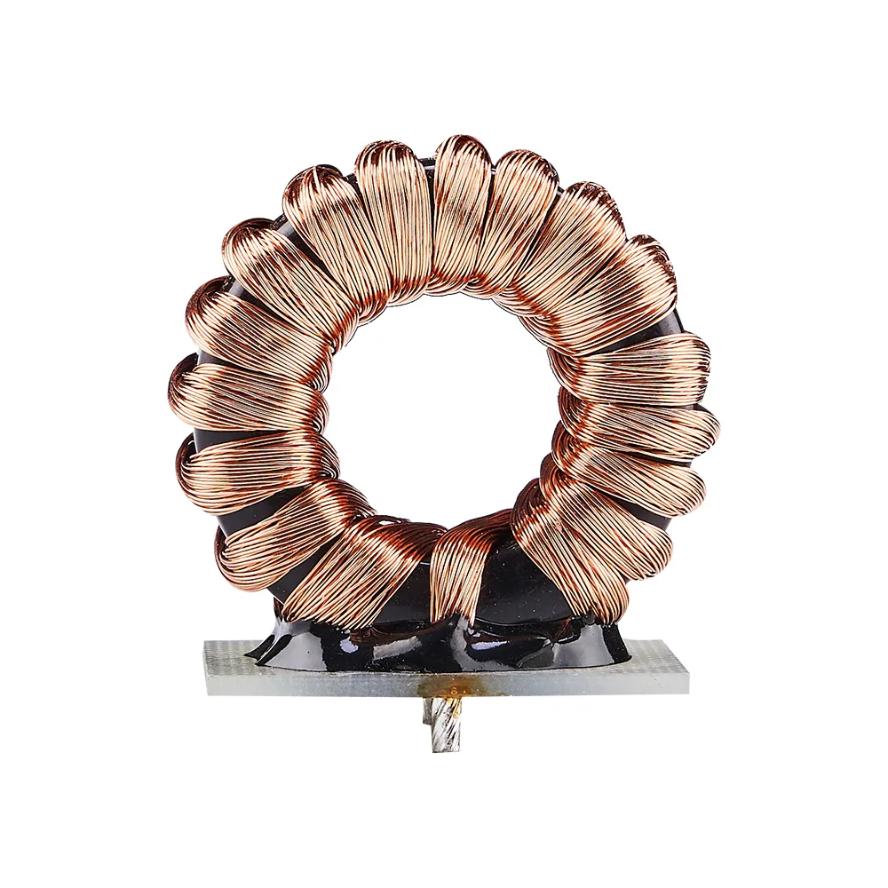
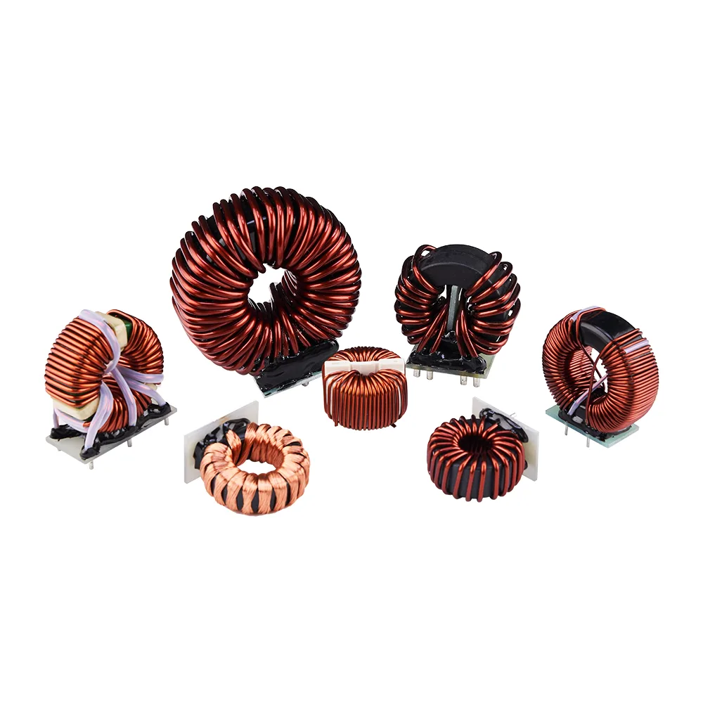
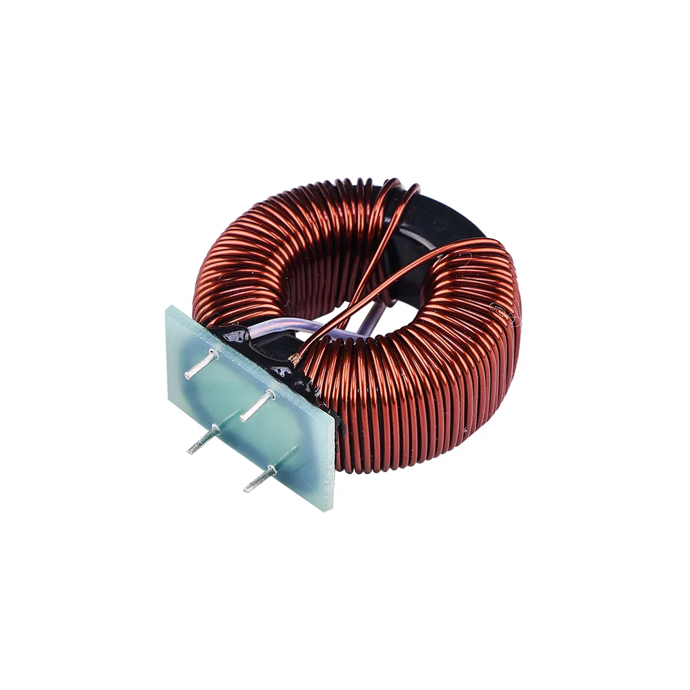
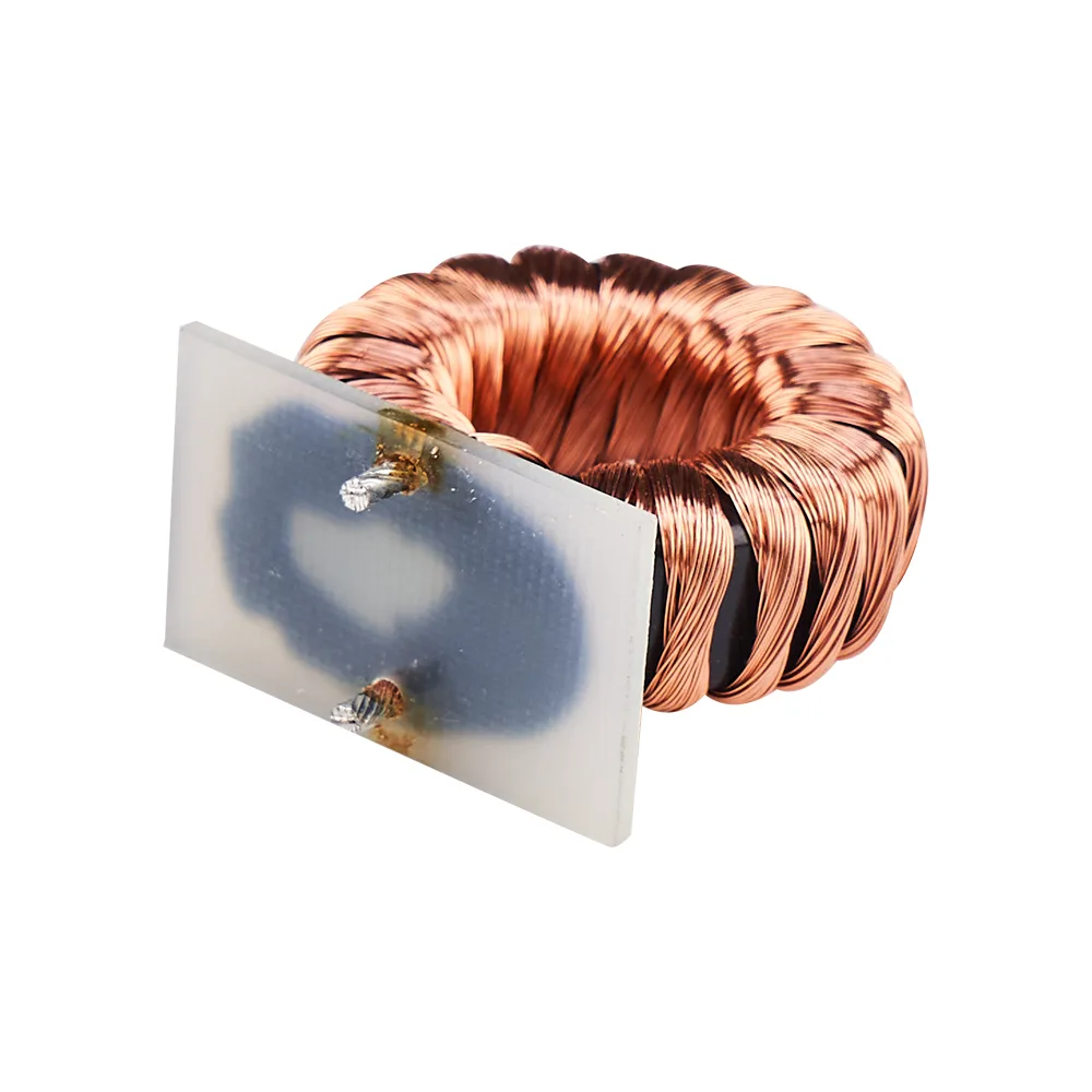
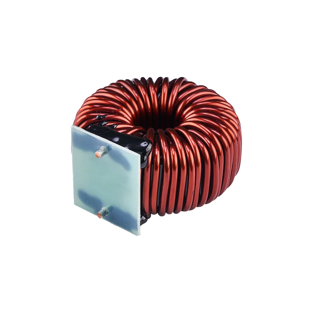
Circular inductors are widely used in power filtering, signal processing, power conversion, and other scenarios due to the unique electromagnetic characteristics brought by the circular magnetic core structure, The advantage of a circular inductor lies in its closed magnetic circuit design (the magnetic core is circular and the winding is evenly wound around the outer circumference). Compared with traditional I-shaped inductors and surface mount inductors, it has significant differences in magnetic efficiency, loss control, and space utilization: 1. High magnetic efficiency, small leakage magnetic pole Magnetic circuit closure without air gap: The magnetic circuit of the annular magnetic core is completely closed (without the “core gap” of traditional inductors), and the magnetic field lines are almost entirely confined inside the core. The leakage coefficient is usually less than 5% (the leakage coefficient of traditional I-shaped inductors can reach 20% -30%), greatly reducing electromagnetic interference (EMI) to surrounding circuits. Example: In a switching power supply, the leakage magnetic interference of a ring inductor is 15-20dB lower than that of an I-shaped inductor of the same power, which can reduce signal interference to peripheral chips (such as MCU). 2. Low power loss and excellent efficiency (both copper loss and iron loss are low) The winding is uniformly wound around the annular magnetic core, with shorter wire length (reduced by 10% -15% compared to resonant inductance), lower DC resistance, and significantly reduced copper loss. The magnetic core uses high-frequency low loss materials (such as iron silicon aluminum, nanocrystals, and high-frequency ferrite), and in the high frequency range of 10kHz-1MHz, the iron loss (hysteresis loss+eddy current loss) is 20% -30% lower than traditional magnetic cores. 3. High power density and compact size At the same power/inductance value, the volume of a circular inductor is reduced by 20% -40% and the weight is reduced by 30% -50% compared to traditional inductors. 4. Stable parameters and strong anti-interference ability Good linearity of inductance: Within 1.5 times the rated current range, the inductance deviation is usually less than ± 5% (traditional inductors may reach ± 10%), especially suitable for filtering scenarios that require high inductance accuracy (such as DC side smoothing of photovoltaic inverters). Excellent vibration resistance and temperature stability: The annular structure has no risk of “magnetic core loosening”, and the working temperature range is wide (-55 ℃~+125 ℃, some industrial grade can reach+155 ℃) 5. Flexible design, adaptable to multiple scenarios It can be customized by adjusting the magnetic core material (iron powder core → iron silicon aluminum → nanocrystals, adapted to different frequency/loss requirements), winding wire diameter (0.1mm-2.0mm, matched with 0.1A-50A current), and number of turns (10-1000 turns, achieving 1nH-10mH inductance), supporting single winding (differential mode) and dual winding (common mode) designs, while also considering various functions such as differential mode filtering, common mode suppression, and energy storage.
☷ Product Advantages
Loop inductors mainly play three core roles in circuits: filtering, energy storage, and signal isolation. Specific application scenarios and corresponding functions are as follows: 1. Power filtering: Suppressing noise and stabilizing voltage By blocking specific frequency currents, noise filtering can be achieved, which can be divided into two categories: differential mode filtering and common mode filtering: ▶ Differential mode filtering (single winding design): It forms high impedance for “reverse transmission differential mode noise” in the line (such as peak currents caused by load transients and grid clutter), and only allows power frequency/DC signals to pass through. Application scenarios: Switching power supply input/output terminals (such as LED driver power supply, laptop charger), industrial frequency converter DC side, reducing ripple voltage (such as reducing output ripple from 200mV to below 50mV). ▶ Common mode filtering (dual winding reverse winding): It forms high impedance for “common mode noise transmitted in the same direction” (such as ground interference and electromagnetic radiation coupling noise) in the circuit, without affecting normal differential mode signals. Application scenarios: Power inlet for household appliances (air conditioners, washing machines), power supply circuit for medical equipment (monitors, ultrasonic devices), in compliance with EMC certification (such as CE, FCC) requirements for common mode interference limits. 2. Energy storage: temporarily storing electrical energy, smoothing power In switch mode power supplies and DC-DC converters, ring inductors serve as “energy storage components” and work together with capacitors to achieve “charge and discharge buffering of electrical energy”, avoiding power fluctuations that affect circuit stability: ▶ Principle: When the switch tube is conducting, the inductor stores electrical energy (with a linear increase in current); When the switch tube is turned off, the inductor releases electrical energy (supplying power to the load through the freewheeling diode), achieving smooth power transmission. ▶ Application scenario: Car DC-DC module (12V to 5V): stores electrical energy with a 100 μ H ring inductor to avoid unstable output voltage caused by voltage fluctuations in the car battery (9V-16V); Photovoltaic inverter: Using a 1mH circular inductor as the energy storage element, matching the intermittent output current of the photovoltaic panel to ensure stable grid connected power. 3. Signal processing: isolation and impedance matching In high-frequency signal circuits, ring inductors achieve signal isolation or impedance matching through electromagnetic induction, reducing signal distortion: ▶ Signal isolation (dual winding design): By utilizing mutual inductance between windings to transmit signals, electrical isolation between the primary and secondary sides is achieved, avoiding signal interference caused by ground potential difference. Application scenario: Signal transmission of industrial sensors (such as pressure sensors and temperature sensors), isolation of ground circuits between industrial control systems and sensors, and improvement of signal acquisition accuracy. ▶ Impedance matching: The high Q value (quality factor, up to 50-100 at high frequencies) of the ring inductor makes it suitable for RF circuits (such as 5G base stations and wireless communication modules). By adjusting the inductance value to match the transmission line impedance (such as 50 Ω, 75 Ω), signal reflection is reduced and transmission efficiency is improved. 4. Current limiting and protection: suppress surge current When starting high-power equipment, the ring inductor can limit the starting surge current and protect circuit components through the characteristic of “inductor current cannot suddenly change”: ▶ Application scenario: Motor starting circuit: A ring inductor is connected in series at the starting end of a three-phase asynchronous motor to reduce the starting current from 5-7 times the rated current to 2-3 times, avoiding the burning of the contactor; ▶ Capacitor charging circuit: In a high-power capacitor charging circuit, a ring inductor is connected in series to suppress the peak current during charging and protect the rectifier bridge.
☷ Application Scenarios
Our reactors are widely used in all industrial fields that require improved power quality and drive protection: ▶ Industrial Automation:VFD input/output terminals for CNC machine tools, industrial robots, and conveyor systems. ▶ Electricity compensation:Connected in series with capacitors, used in reactive power compensation cabinets (SVG/SVC) to form a tuned filtering circuit to prevent harmonic amplification. ▶ Heavy industry sector:High power and high load power systems such as lifting equipment, metallurgical rolling mills, mining crushers, and large fans and pumps. ▶ New Energy:Photovoltaic inverter stations and wind power conversion systems are used to smooth the output current and meet grid connection requirements. ▶ Infrastructure:Central air conditioning, elevators, water pumps and other building automation systems ensure stable operation of public facilities.
☷ Product Display
Join us and look forward to discussing with you!